by Randy Minter
edited by Kristen Fredriksen
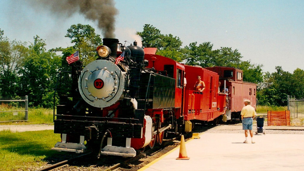
The illustration below shows a simplified side view of Georgia Power #97, the 0-6-0 tank engine that operated at the Southeastern Railway Museum during the April to November season through the early 2000s. With Mack (Jeddo Coal Co. #85) coming to visit on September 29-30 and October 6-7, we thought we should provide some background. How does a steam engine work? Compare the numbered items in the drawing with the descriptions that follow, and you will know… The Basics.
The tank (1) contains water to make the steam which moves the engine and its train. The water is heated to boil off as steam in the boiler (2).
Within the boiler is the throttle valve which is operated from the cab (5). The steam leaves the throttle and travels by pipe to the cylinders (3). The cylinders contain valves that allow the engine to go both forward and backward. The cylinders also contain pistons that deliver the power of the steam–by connecting rods–to the driving wheels (4).
After the steam is used by the pistons, it exhausts out the stack above the cylinders, which is where steam locomotives get their chugging sound.
To make trains more reliable and safe, air brakes were developed. Steam driven air compressors (7) supply the air for the system. Controls for both the engine brakes and the train brakes are located inside the cab. The brake cylinder (8) uses air via a series of fulcrums and rods to slow down and stop the engine. Hoses at both ends of the engine supply compressed air for the brakes on the cars on the train.
Power for the locomotive’s cab lights and headlights is supplied by a turbine generator (9) in front of the cab. The generator is commonly called a dynamo by railroaders and has a distinctive whine.

Once a coal burner, #97 was converted to burn No. 2 fuel oil which is located in a tank (6) behind the cab. The fuel is burned as needed to keep up enough steam to operate the locomotive. The fire is manually controlled by a fireman with controls inside the cab.
Engine efficiency is improved by sand that is fed as needed from the dome (10) onto the rails to provide better traction during heavy pulls or adverse conditions.
The couplers (11) are, perhaps, one of the most important parts of the locomotive. They make it possible for the locomotive to push or pull the train.
One item is not numbered and it is generally the first thing you hear: the whistle. If you can’t find it on the drawing, you’ll have no trouble finding it on the locomotive itself.
One last important component not pictured: the crew. The engineer sits on the right side of the cab, the fireman on the left. Between trips, you will find them busy with wrenches, oil cans, and water hoses. While they might stand still long enough for a photograph, they would much prefer to talk about their locomotive and the power of steam.
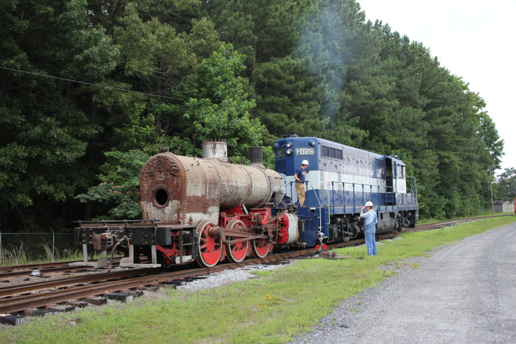
Where is 97 now? Awaiting restoration!


Just curious but when will 97’s restoration be complete? I visited the museum in late 2024 and saw 97 in the workshop while on the caboose ride and it seemed that the only thing left to do was to reattach 97’s side tanks to the boiler.
Levi, thanks for the note. 97 is slowly coming along in its cosmetic restoration. Still to come is piping, painting, cab interior, the tanks and more. It’s a volunteer effort, and we’re balancing a lot of things at the moment. Thanks for the visit!